In-scattering for spot lights
Table of Contents
In short
This post will cover my work on light scattering in game Guiding Light developed using DirectX 11 for ZTGK 2024 competition. Our work was awarded the main prize in the Game Development category and received a special award from Activision.
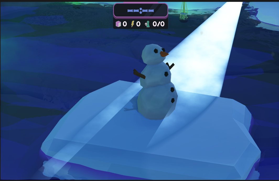
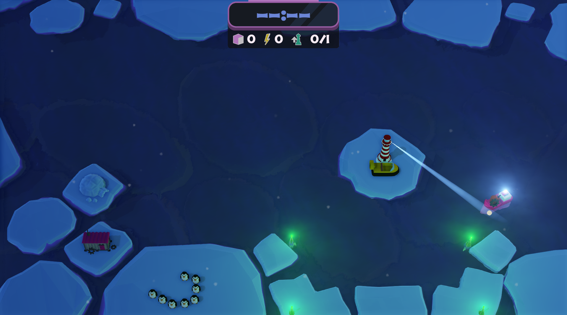 Picture showing the results of my work.
Chosen method
I needed to find a method that wouldn’t take me much time to implement. We were tasked with making a game in parallel with it’s own game engine in 3 months, there wasn’t much time for sophisticated methods, nor was it necessary given the overall theme of our game.
After some extensive research I stumbled upon a blog post made by Miles Macklin called In-scattering demo which suited my needs perfectly.
What did I do and how?
Macklin’s solution covered most of my needs, with one exception. Light scattering didn’t take into account occluders, which was very crucial to me, lighthouse’s light was the center-point of entire gameplay, a light that goes through occluders would be unacceptable. I will explain my solution in a later section. First, I want to shine some light on what Macklin did, but did not explain in his blog. Next few sections will explain step-by-step how to achieve the scattering for spot lights.
Scattering equation
Macklin explains the theory behind it quite well, moreover he provides a GLSL snippet for the code. I made one change to it (other than rewriting in HLSL):
float in_scatter(float3 start, float3 dir, float3 lightPos, float d)
{
    // Calculate quadratic coefficients a, b, c
    float3 q = start - lightPos;

    float b = dot(dir, q);
    float c = dot(q, q);

    float denominator = c - b * b;

    // Avoid division by zero or very small values
    if (denominator < 1e-6)
    {
        return 100000.0f;
    }
    // Evaluate integral

    float s = 1.0f / sqrt(denominator);
    float l = s * (atan((d + b) * s) - atan(b * s));

    return l;
}
I added a check if the value of the denominator is a zero, the absence of this check produced some nasty artifacts.
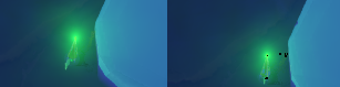
On the left you can see the corrected version, on the right the one with artifacts.
Spotlight cone
How do we check if a point is inside the cone of the light? Maths! We need a cone equation which is:
\[ x^2 + z^2 = y^2 \cdot tan^2(θ) \]or as a quadratic equation:
\[ x^2 + z^2 - y^2 \cdot tan^2(θ) = 0 \]Theta (θ) is the cut-off angle of the cone. (if you don’t understand the equation look into Geogebra).
For every pixel we will be casting a ray from the camera towards it. Later we will determine if the ray intersects with the cone. Given an origin point O and direction D, a point along the ray can be represented by:
\[ P(t) = O + t \cdot D \]So let’s substitute the point along the ray into our equation:
\[ (O_x + t \cdot D_x)^2 + (O_z + t \cdot D_z)^2 - (O_y + t \cdot D_y)^2 \cdot tan^2(\theta) = 0 \]After you raise everything to the power of 2 and group all terms by powers of t you will get a quadratic equation of:
\[ a = D^2_x + D^2_z - D^2_y \cdot tan^2(\theta) \] \[ b = 2 \cdot (O_x \cdot D_x + O_z \cdot D_z - O_y \cdot D_y \cdot tan^2(\theta)) \] \[ c = O^2_x + O^2_z - O^2_y \cdot tan^2(\theta) \]Solving it will give you the ray’s intersection points with the cone. We will later use distance between those two points to determine the scattering strength. Here’s how the function looks like:
// This is mostly taken from Macklin's blog
float2 intersect_cone(SpotLight light, float3 origin, float3 direction)
{
    // Transform to light's local space
    float4 local_origin = mul(light.inv_model, float4(origin, 1.0f));
    float4 local_direction = mul(light.inv_model, float4(direction, 0.0f));

    // calculate the a, b and c with the provided formula here:
    float a,b,c;

    float min_t = 0.0f;
    float max_t = 0.0f;
    solve_quadratic(a, b, c, min_t, max_t);

    float y1 = local_origin.y + local_direction.y * min_t;
    float y2 = local_origin.y + local_direction.y * max_t;

    if (y1 > 0.0f && y2 > 0.0f)
    {
        // Both intersections are in the reflected cone
        // so return degenerate value
        min_t = 0.0f;
        max_t = -1.0f;
    }
    else if (y1 > 0.0f && y2 < 0.0f)
    {
        // Closest t on the wrong side,
        // furthest on the right side
        // => ray enters volume but doesn't leave it
        // (so set max_t arbitrarily large)
        min_t = max_t;
        max_t = 10000.0f;
    }
    else if (y1 < 0.0f && y2 > 0.0f)
    {
        // closest t on the right side,
        //largest on the wrong side
        // => ray starts in volume and exits once
        max_t = min_t;
        min_t = 0.0f;
    }

    return float2(min_t, max_t);
}
As you probably noticed, we need to handle some edge cases, but I think the code is pretty self-explanatory.
Finally, having done all this we can calculate how much light is scattered between the pixel and camera.
float3 calculate_scatter(SpotLight light, float4 world_position, int light_index)
{
    float3 surface_to_camera_direction = world_position.xyz - camera_pos;
    float ray_length = length(surface_to_camera_direction);
    surface_to_camera_direction /= ray_length;

    float min_t = 0.0f;
    float max_t = 0.0f;

    float2 res = intersect_light_cone(light, camera_pos, surface_to_camera_direction);
    min_t = res.x;
    max_t = res.y;

    max_t = clamp(max_t, 0.0f, ray_length);
    min_t = max(0.0f, min_t);

    float t = max(0.0f, max_t - min_t);

    // This is arbitrary. I needed a very strong scattering efect, hence the multiplication
    float scattering_coefficient = 100.0f * light.scattering_factor;

    float3 scattering_constants = float3(0.2f, 0.4f, 0.8f);
    float3 scatter = light.diffuse * scattering_constants
                            * in_scatter(camera_pos + surface_to_camera_direction * min_t, surface_to_camera_direction, light.position, t)
                             * scattering_coefficient;

    return scatter;
}
You probably noticed the scattering_constants variable. What does it do? Why it’s blue component is the highest? It’s because we want to simulate Rayleigh scattering, which causes the sky to be blue (this is a major simplification, the sky is yellowish/redish during sunset, but these coefficients will work for our case).
Last step is adding the scatter to already calculated pixel color (scattering here is a postprocess).
What about the shadows?
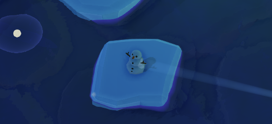
If you have implemented everything correctly, the result should look like that:
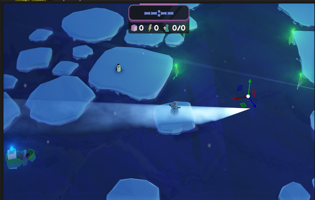 Notice anything wrong? Yes, the cone is going through the snowman! We need to introduce some shadows.
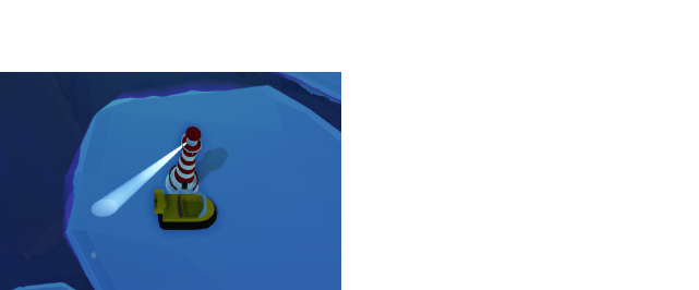
We have the intersection points with the cone, why not calculate if this point is in the shadow?
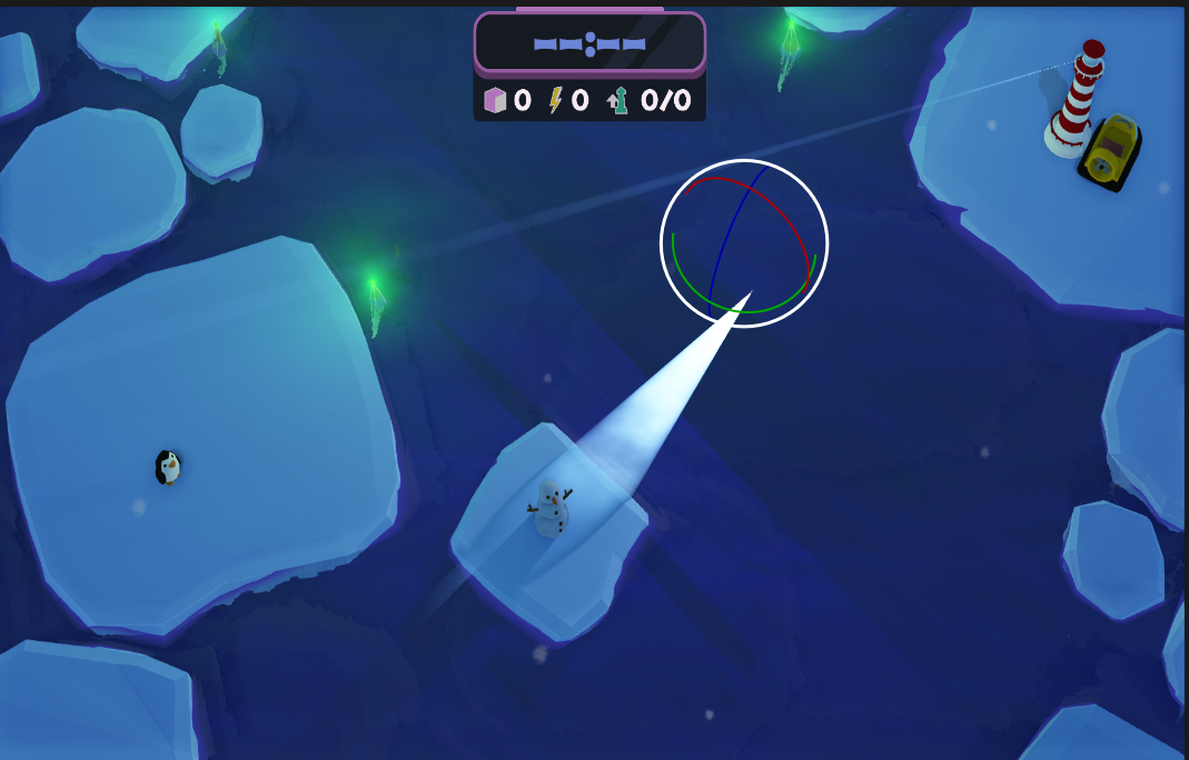 Looks plausible doesn’t it? Let’s try and test it further.
 Now we see that this is flawed. Cone makes the impression of being empty.
I am ashamed to admit I chose to use this solution, the game was dynamic enough and camera angle was minimizing the artifacts (empty cone).
Is there any way to fix it?
I think there is. You could, in such situations, ray-march between the intersection points and calculate the shadow (could be a bit costly) and later average it. If you implement it, lemme know on Twitter @umbc1ok.
The noise on the fog
The noise you see on the fog is not natural, it’s a trick I used. Normally scatter will just fade-out when it’s farther away from the light source and that’s it. This makes the cone look too regular for me, I used a noise texture that I scrolled through the screen to apply some distortions to the fog. Note that it only works because the camera in our game is static, otherwise it would be very unpleasant to look at.
That’s how it looks without the noise on:
Optimization?
During ZTGK I got a chance to meet some great graphics programmers and they asked me a looot of questions. The best part for me was that I didn’t have any issues with finding answers to them, which helped me with getting rid of the impostor syndrome, at least a bit. There was however one question that I couldn’t answer, which seriously boggled me. The question was: How do you draw the geometry of those lights?
Well, my answer was: I use the cone’s equation to check if a ray intersects with it. It was actually not what the question was about, he was looking for some geometry that will be literally drawn with a draw call.
A few weeks later I was reading Adrian Courrèges’ blog about reverse engineering GTA V’s rendering pipeline and came across this image:
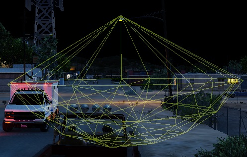
And that’s where I realized what was his question about. I could render a mesh that would have a shape of a cone (or a sphere in case of point lights) and use it to determine which pixels are affected by scattering. That would be a huge optimization and it’s also something I probably should have done to utilize deferred rendering better.
Ending notes
I would like to especially thank Miles Macklin for his blog on this subject. Remember that this post is mostly an explanation of what Miles did, but didn’t explain himself. I also wanted to dig this method out of the abyss (the blog is from 2012!).
comments powered by Disqus